HomeTechnical DocumentationOptimization of Comb-Type Cages for Four-Row Cylindrical Roller Bearings: Enhancing Assembly Efficiency and Performance
Technical Insights
Optimization of Comb-Type Cages for Four-Row Cylindrical Roller Bearings: Enhancing Assembly Efficiency and Performance
Published: Mar 07, 2026
Engineering Team
1. Background and Structural Analysis
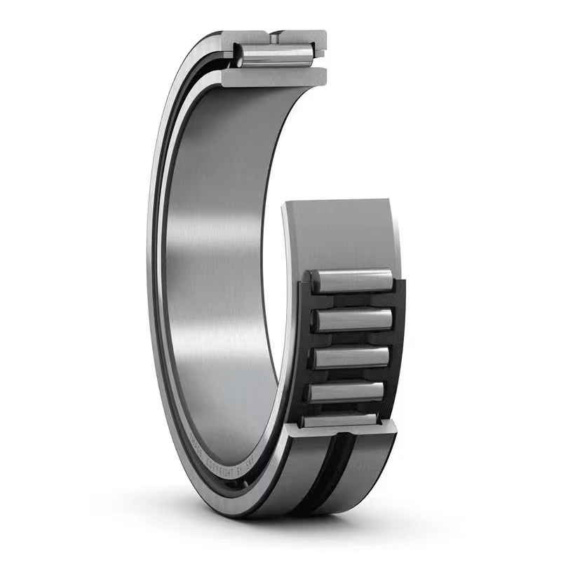
Four-row cylindrical roller bearings used in rolling mills typically come in FC, FCD, and FCDP configurations. For bearings with an outer diameter under 500mm, the FC type is the most common.
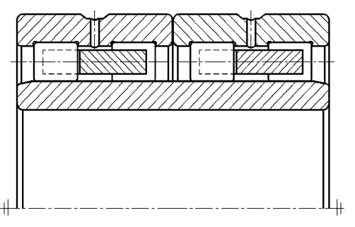
Traditional Design: These bearings utilize a solid brass comb-type cage. The outer ring features a double flange with a filling slot on one side.
Guidance Mechanism: The cage is guided by the inner diameter of the outer ring flange, with a typical clearance of 0.5–1mm. Consequently, the cage's outer diameter ( DcDc ) is slightly smaller than the flange's inner diameter ( D2D2 ).
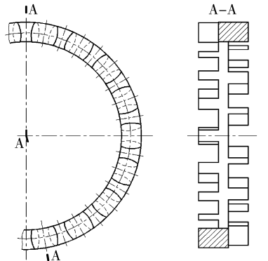
Description: Diagram showing the FC type bearing structure and the pre-improvement cage. It illustrates the standard assembly where the cage guides the rollers within the outer ring.
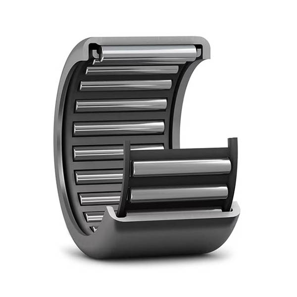
2. Problem Identification
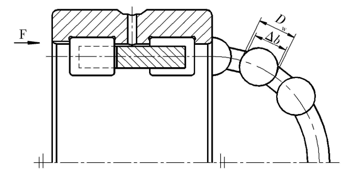
The primary issue arises during the assembly process when rollers are inserted into the raceway through the filling slot.
Excessive Containment: In the traditional design, the cage's outer diameter creates a large "containment capacity" over the rollers. This results in a radial locking amount ( δδ ) of approximately 6mm.
Assembly Difficulties: Due to this excessive lock, rollers are difficult to insert, often requiring forceful hammering with copper mallets.
Consequences:
Surface Damage: Severe scratching occurs on the outer raceway surface, which cannot be repaired once internal.
Debris Generation: High shearing forces between the roller ends and the cage pocket walls generate copper debris, contaminating the bearing interior.
Performance Impact: This debris and damage severely affect rotational accuracy and reduce service life.
Operational Inefficiency: The process increases labor intensity and lowers production efficiency.
Description: Internal structural relationships highlighting the interference during roller insertion.
3. Structural Improvements
To resolve these issues without compromising the bearing's operational safety (preventing rollers from falling out), the authors proposed a modified cage design.
Design Logic: Since the locking amount provided by the outer ring flange cannot be reduced, the solution lies in reducing the cage's containment capacity over the rollers.
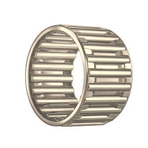
Modified Geometry:
The guiding outer diameter ( DcDc ) remains unchanged to ensure proper guidance.
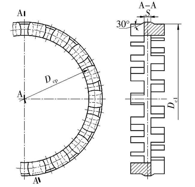
The outer diameter at the pocket area ( Dc1Dc1 ) is reduced.
A 30° angle connects DcDc and Dc1Dc1 to enhance strength at the pocket root.
Typically, the difference between the pocket center diameter and the reduced outer diameter ( Dcp−Dc1Dcp−Dc1 ) is set between 10–13mm.
Description: The improved comb-type cage, showing the stepped profile that reduces interference during assembly.
Results: This modification reduces the radial locking amount ( δ′δ′ ) to 1–1.5mm, which satisfies the minimum design requirement of 1mm while drastically easing installation.
4. Conclusion and Benefits
The implementation of the improved cage structure has yielded significant benefits:
✅ Fundamental Solution: It effectively eliminates the assembly difficulties inherent in the original design.
✅ Quality Improvement: Marked reduction in raceway scratching and internal debris, leading to better rotational flexibility and extended bearing life.
✅ Efficiency: Lower labor intensity and higher production efficiency due to easier roller insertion.
✅ Cost Reduction: The design reduces the cage's self-weight, thereby lowering manufacturing costs.
This optimization represents a practical engineering solution that balances assembly manufacturability with high-performance operational requirements.
Need implementation support?
Industrial Experts On-Call
"Facing specific rotation or lubrication challenges? Our engineers can provide free consultation based on your machinery specs."
We use cookies to enable the "Inquiry Basket" feature and analyze traffic. By clicking "Accept All", you consent to our use of cookies. View our Privacy Policy and Cookie Policy.