Why Your Bearing Fails Prematurely,The Hidden Science of Internal Clearance
The Critical Misconception: "CN is Universal"
In many workshops, a common habit persists where engineers default to selecting bearings with CN (Normal) Clearance, reserving other options only for extreme temperature applications. However, this approach overlooks a fundamental physical reality: A bearing’s internal clearance changes drastically from the moment it is mounted and heated.
The clearance listed in catalogs is merely the Initial Clearance, measured at ambient temperatures without load. It is the actual Operating Clearance—the state of the bearing under rotating load and thermal expansion—that ultimately determines whether the machine runs quietly or suffers a premature failure due to brinelling or excessive heat generation.
The Mathematical Model: How Clearance is "Consumed"
To select the correct initial clearance, one must understand that the operating clearance ( ΔworkingΔworking ) is not a static value. It is calculated by subtracting specific "losses" from the initial clearance ( ΔinitialΔinitial ). These losses are primarily driven by two physical phenomena: the mechanical expansion from fitting and the thermal expansion from operation.
First, consider the loss due to Interference Fit ( δfitδfit ). When a bearing is pressed onto a shaft, the inner ring expands to accommodate the shaft's diameter. This expansion inevitably reduces the internal radial clearance. As a rule of thumb, the reduction in clearance is approximately 70% to 90% of the effective interference value. For instance, if a shaft has an interference fit of 0.02mm, roughly 0.014mm to 0.018mm of the bearing's internal clearance is consumed immediately upon mounting.
Second, there is the loss due to Temperature Differential ( δtempδtemp ). During operation, the inner ring—attached to the rotating shaft—is almost invariably hotter than the outer ring, which sits in the housing. As metals expand with heat, the inner ring grows larger, further reducing the internal clearance. This thermal reduction can be estimated using the coefficient of thermal expansion for steel, the temperature difference between the rings (typically 5∘C5∘C to 10∘C10∘C ), and the raceway diameter.
Engineering Decision Matrix: Navigating C3, C4, and CN
Based on the calculation logic above, we can establish clear guidelines for different industrial scenarios without relying on guesswork.
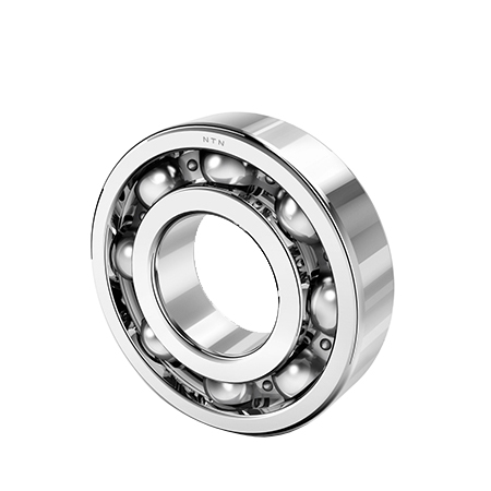
For Standard Industrial Motors, the industry standard has shifted toward C3 clearance. While one might assume Normal (CN) clearance is sufficient, standard motors typically utilize k6 or m6 fits on the shaft. This interference fit alone consumes the majority of the CN clearance. If a CN bearing is used in this context, it effectively runs with negative clearance (or preload), leading to rapid overheating and failure. Therefore, C3 is necessary to compensate for the fit.
In contrast, Vibrating Screens and Crushers operate under much more severe conditions. These machines rely on the bearing to accommodate misalignment and the dynamic forces of vibration. Furthermore, the vibration itself generates significant heat. In these cases, even C3 clearance is often insufficient. Engineers should specify C4 or C5 clearance, ensuring the bearing starts with a large enough internal gap so that it does not go negative during peak operation.
For Mounted Units (Pillow Blocks), C3 clearance is also the standard recommendation. Similar to motors, the interference fit on the shaft reduces clearance. Additionally, the housing bore in these units often possesses slight ovality; the extra clearance in a C3 bearing helps compensate for this geometric imperfection.
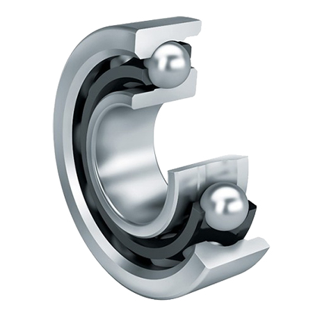
However, distinct rules apply to High-Speed Spindles and Paired Angular Contact Bearings. High-speed spindles generate immense heat but often require tighter tolerances; here, C2 (less clearance than normal) might be used if the fit is loose, though this requires precise thermal calculation to avoid seizure. Meanwhile, paired angular contact bearings are generally not selected by radial clearance codes like C3 or C4. Instead, they are selected based on axial preload requirements to achieve a specific "zero" or controlled "light" operating clearance.
The "Zero" Goal and the Danger of "Negative"
The ultimate goal of any clearance selection strategy is to achieve a slightly positive operating clearance when the machine is running at full temperature and load. This "sweet spot" ensures that the rolling elements roll freely without skidding and that a perfect oil film can form.
Conversely, falling into the "Danger Zone"—where the calculation results in a negative number—is catastrophic. This means the rings are being forced apart by the rolling elements, creating a state of constant preload. Under these conditions, the stress on the raceway can exceed the yield strength of the steel, leading to False Brinelling, Heat Checking, and rapid fatigue. Therefore, for critical equipment, never guess; calculate the effective interference and estimate the temperature rise to ensure your bearing survives the transition from the shelf to the shaft.